
In order to design feasible and well-functioning geothermal borefields, it is important to understand the thermal behaviour of the system. In this article, we will look at the effective borehole thermal resistance as a means to model the short-term thermal behaviour of borefields.
Thermal behaviour
When designing borefields, we want the average fluid temperature to remain within certain temperature limits, so it is very important to understand how these fluid temperatures are calculated. (If you have not read our article specifically on interpreting temperature plots, you can find it hier.) Looking at the plot below, you can observe two different trends:
-
A seasonal and yearly variation in the borehole wall temperature
- A certain difference between the borehole wall temperature and the mean average fluid temperature
The first effect relates to the long-term thermal behaviour of borefields (which will be covered in a follow-up article), while the second concerns the short-term effects.
If we want to reduce the required borefield size, we aim to minimise the temperature difference between the borehole wall temperature and the average fluid temperature. But how do we calculate this temperature difference?

The average fluid temperature can be calculated as follows:
$\overline{T_f}(t)=\overline{T_b}(t)+\dot{q}(t) R_b^*$
where $\overline{T_f}$ is the average fluid temperature, $\overline{T_b}$ the borehole wall temperature, $\dot{q}$ the power per meter borehole and $R_b^*$ the effective borehole thermal resistance. These parameters are also shown schematically on the figure below.

This means that, at every instance $t$, the average fluid temperature is defined as starting from the borehole wall temperature plus or minus a certain $\Delta T$, which arises from the power per unit length multiplied by the resistance. On the short time scale where this peak fluid temperature occurs, we can assume the borehole wall temperature to be constant, so the fluid temperature depends only on these two parameters.
Effective borehole thermal resistance
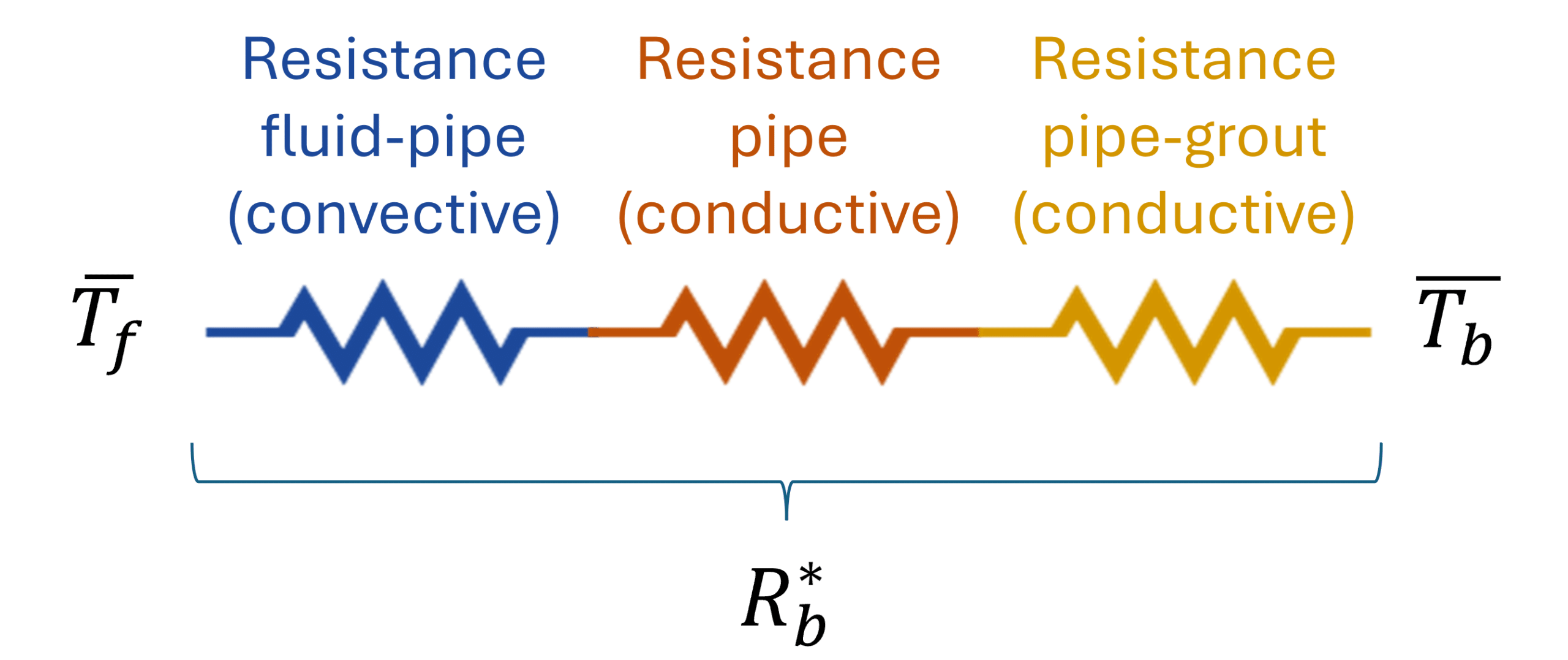
This effective borehole thermal resistance is therefore a parameter used to model the temperature of the fluid inside the borefield and can be visualised as a sum of three resistances that the heat must pass through to travel from the fluid to the ground:
-
From the fluid to the pipe (convective heat transfer)
-
Through the pipe (conductive heat transfer)
-
Through the grout to the borehole wall (conductive heat transfer)
We will discuss each of these sub-resistances below.
Let op
The effective borehole thermal resistance is actually much more complex to calculate, as there are also thermal short-circuits between the different legs of a U-tube, for example. However, for the purpose of this article—which is to gain insight into which parameters influence the short-term behaviour of the fluid temperature—the approximation below is sufficient.
Let op
There is a difference between the effective borehole thermal resistance and the (local) borehole thermal resistance. The effective borehole thermal resistance considers the borehole as a whole, whereas the local borehole thermal resistance only looks at the cross-sectional thermal resistances. All resistances within GHEtool (and for example also the resistance measured during a TRT) are effective borehole thermal resistances.
Fluid-pipe resistance
The first important term in the effective borehole thermal resistance relates to the convective heat transfer from the fluid to the pipe. This is highly influenced by the flow regime of the fluid. A laminar flow (with Reynolds numbers below 2300) has a significantly higher convective heat resistance than a transient or turbulent flow (Re > 2300). This is a parameter you can adjust in your specific design.
Let op
If you have not read our article on the Reynolds number, you can find it hier. We also wrote an article about the differences between GHEtool and Earth Energy Designer (EED), which you can consult hier.

The graph above shows how the effective borehole thermal resistance changes as the flow rate (and therefore the Reynolds number) increases. You can see that once it passes the laminar–transient boundary, the resistance decreases significantly, until it becomes almost constant in the fully turbulent regime (Re > 4000). It is also visible that EED assumes the flow transitions from laminar to turbulent immediately, without considering the transition zone.
Let op
In order to calculate the Reynolds number, the reference fluid temperature is needed at which the fluid properties will be calculated. Within GHEtool, this reference temperature is equal to the minimum average fluid temperature threshold you set in the ‘General’ tab.
Pipe-resistance
This resistance is determined by the thermal conductivity of the pipe wall and is typically not something we as designers have much influence over. Around 99% of all geothermal heat exchangers are made from PE, which has a thermal conductivity of approximately 0.4 W/(mK). The wall thickness, on the other hand, is a parameter we have a bit more influence on, but it is usually dictated by the required pressure class. For example, if you have a borehole that is 150 m deep, you will want the pipes to withstand a pressure of 16 bar. In that case, you would use a PN16 pressure class, which in turn determines the wall thickness. Below, you can find some typical wall thicknesses.
| Pipe | Wall thickness |
|---|---|
| DN32 PN16 | 3 mm |
| DN40 PN16 | 3,7 mm |
| DN50 PN16 | 4,6 mm |
Pipe-grout resistance
The last resistance the heat must pass through is the resistance from the pipe, through the grout, to the borehole wall. Here again, there are several parameters we can influence.
Distance between the pipe and the borehole wall.
The closer the different legs of the U-tube are to the borehole wall, the lower this resistance will be, as the heat has less grout to pass through. However, this is not something that can be easily measured or predicted. In general, it can be said that if you work with a smaller borehole diameter, this component of the pipe-to-grout resistance will also be lower. That said, borehole diameter is often limited and determined by the geological conditions at your specific location. As a general rule of thumb, we suggest placing the U-tubes halfway between the borehole centre and the borehole wall (see graph below).
Let op
In addition to thermal conductivity, the pumpability of the grout is also important in practice, since it must reach the bottom of the borehole. Please consult your drilling company to confirm which type of grout they are using.
Grout thermal conductivity
Another important factor is the grout’s thermal conductivity. The higher this conductivity, the lower the resistance for heat transfer through the borehole. Typically, this value ranges from 0.6 W/(mK) up to 2.5 W/(mK) for thermally enhanced grout, where materials such as graphite are used to improve thermal properties. This can have a significant impact on your geothermal design, but also on your installation cost, as grouts with better thermal conductivity tend to be more expensive.
Let op
Next to the thermal conductivity, also the pumpability of the grout is important in practise, since it has to go to the bottom of the borehole. Please check with your drilling company which grout they are using.

Double U-tube
If you are working with a U-tube, installing a double U-tube can reduce the pipe-to-grout thermal resistance, as the increased surface area allows for more efficient heat transfer.
Let op
However, using a double U-tube instead of a single U-tube will not necessarily lead to a lower overall borehole thermal resistance, because the fluid regime can differ between the two configurations. It is therefore important to consider all the different resistances before drawing any conclusions.
Power per unit length
When we look back at our formula for the average fluid temperature ($\overline{T_f}(t)=\overline{T_b}(t)+\dot{q}(t) R_b^*$), we have so far only discussed the $R_b^*$, but the $\dot{q}(t)$ is equally important. If we want to extract x kW from 100 m of borehole, the specific heat extraction power will be x/100 kW/m. This will result in a certain $\Delta T$ between the borehole wall temperature and the average fluid temperature. However, if we increase the borehole length to 200m, this $\dot{q}(t)$ will be halved, leading to half the $\Delta T$ as well.
For the short-term effect, it is therefore very important to have enough metres of borehole, where ‘enough’ is determined by your temperature limitations.
Let op
Note that for the short-term effect, the position of these boreholes does not matter much, only the total borehole length. The position will become important when we talk about the long-term thermal effects in the next article.
Final remarks
There are two aspects that have not yet been included in the analysis above: the thermal inertia of the grout and fluid, and the case of groundwater-filled boreholes. These will be briefly touched upon below, although each topic will be covered in a separate article.
Thermal inertia
Up to this point, we have discussed the effective borehole thermal resistance as a way to calculate the temperature difference between the borehole wall and the mean fluid temperature. However, this is based on what we call a steady-state model. If we extract x kW of power from the borehole, this model assumes an immediate drop in fluid temperature, proportional to the effective borehole thermal resistance. In reality, it is first the fluid that cools down, followed by the grout, and finally the ground. Therefore, the immediate temperature spikes—especially on short timescales of hours—are somewhat conservative when using this approach.
Blijf op de hoogte
We are currently working together with The SySi team at KU Leuven to develop a more accurate model that takes this dynamic behaviour into account.
Groundwater-filled boreholes
Earlier, we mentioned the impact of grout thermal conductivity on the effective borehole thermal resistance. However, not all boreholes are grouted. In Sweden, for example, boreholes are typically drilled into rock and left ungrouted, meaning the filling material is groundwater. This introduces more complex physical phenomena, as grout is a solid and transfers heat only by conduction, whereas groundwater can move vertically in the borehole, introducing advective heat transfer. To complicate things further, the water can also freeze, introducing latent heat transfer.
There are some correlations available on how to model these groundwater-filled boreholes and how to use a tool like GHEtool to calculate them, but this is a topic for another article.
Conclusie
Understanding and accurately modelling the effective borehole thermal resistance is crucial when designing efficient geothermal borefields, particularly for capturing short-term thermal behaviour. This parameter encapsulates the complex interplay between fluid dynamics, pipe characteristics, grout properties, and borehole configuration. By optimising factors such as flow rate, grout conductivity, and borehole length, designers can reduce the temperature difference between the borehole wall and the heat transfer fluid, ultimately improving system performance and potentially reducing the required borefield size.
Our next article will discuss the long-term thermal effects of the borefield, taking into account seasonal variations and yearly imbalance. Stay tuned!
References
- Watch our video explanation over on our YouTube page by clicking hier.