
Within GHEtool, you have the highest flexibility for borefield design. In this article, we show you how to export coordinates from a DWG file using AutoCAD and import them directly into GHEtool Cloud, allowing you to create the most accurate representation of your borefield in just a few minutes!
Design with coordinates
While GHEtool already provides great flexibility in creating regular borefield configurations (such as rectangular, U-shaped, L-shaped, or dense layouts), many modern projects are simply too specific to fit neatly into one of these categories. Imagine, for example, a site with multiple borefields scattered across a large area, or a borefield that partially lies beneath a building. These cases require a more advanced approach to borefield modelling — and with GHEtool, this is now easier than ever, especially if you’ve already drawn your borefield layout on a map.
Let op
Using the exact borefield configuration, instead of approximating it with a regular pattern, allows for more accurate calculation of borehole-to-borehole interaction, which directly affects the long-term behaviour of the borefield. For more details, see our article on the long-term borefield physics.
Export coordinates in AutoCAD
1. Open your DWG file containing the coordinates in AutoCAD.
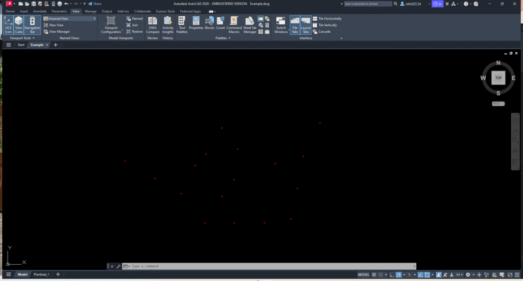
2. Type DATAEXTRACTION in the command line to open the Data Extraction dialog box.
3. Select ‘Create a new data extraction’ and press Next. A pop-up window will appear where you can choose a location to save the data extraction file. You can delete this file afterwards, as it is not required by GHEtool.
4. On the next screen, select ‘Select objects in the current drawing’.
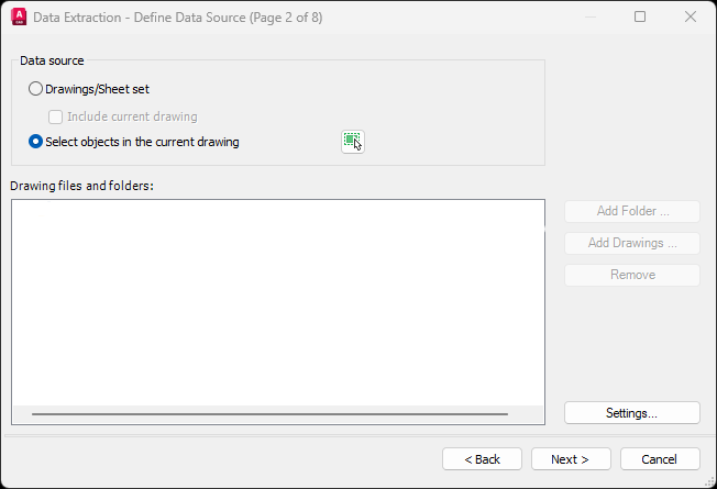
5. Click the selection icon to return to your DWG file and manually select the coordinate objects. Click once to start the selection rectangle, drag over your borehole markers, and click again to finish the selection. Press Enter to return to the Data Extraction dialog. Click Next.
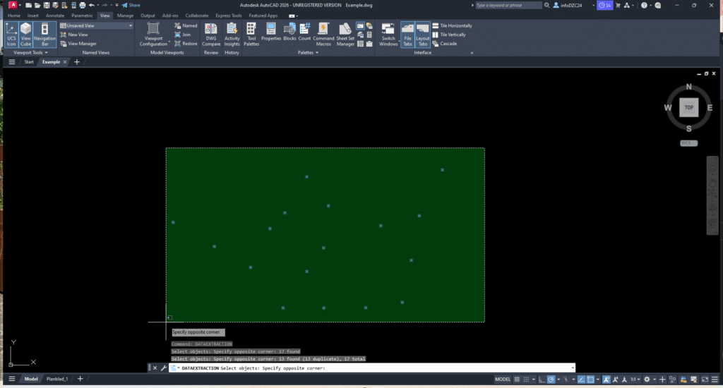
6. Select the objects you want to export. In most cases, boreholes are marked as XCROSS objects. Deselect any object types that are not relevant. Click Next.

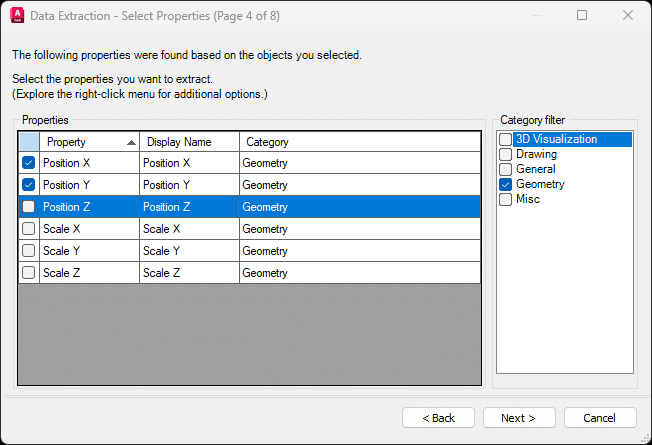
7. On Page 4 of 8, you will be prompted to select which properties to extract. We’re only interested in the geometry parameters, specifically the Position X and Position Y coordinates. Deselect all other parameters. Click Next.
Let op
If your borefield contains boreholes with different buried depths, you may also export the Position Z. However, to import these correctly into GHEtool, you’ll need to manually add a column to the CSV file to specify either borehole depth or borehole length (see next section for details).
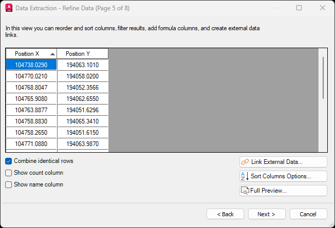
8. On Page 5 of 8, refine the data export by deselecting the options to include the Count column and the Name column. Click Next.
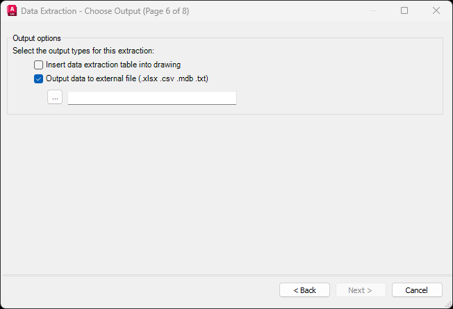
9. On Page 6 of 8, choose ‘Output data to external file’ and use the three dots to browse and select where to save the file. Click Next.
10. Click Finish, and your borehole coordinates will be exported to a CSV file.
In the next step, we’ll show you how to import these AutoCAD coordinates directly into GHEtool Cloud.
Custom borefields in GHEtool Cloud
There are two different ways to work with custom borefields in GHEtool Cloud. One option is to import a CSV file with coordinates (created manually or exported from AutoCAD as described above). The other is to start from a regular configuration and adapt it to fit your specific layout. Both approaches are explained below.
Import coordinates into GHEtool Cloud
GHEtool Cloud offers three levels of custom borefield modelling:
- All borefields have the same depth and buried depth. This gives two degrees of freedom for each borehole: x and y position.
- Each borehole has its own depth and/or buried depth. This gives four degrees of freedom: x, y, depth, and buried depth.
- Each borehole can have its own tilt and orientation. This gives six degrees of freedom: x, y, depth, buried depth, tilt, and orientation.
Depending on which level you want to model, you will need to include the appropriate columns in your CSV file. For example, if you exported only the x and y positions from AutoCAD but want each borehole to have a different depth, you must manually add the relevant columns to the file.
!Hint
Next to the file input box, there is a template button where you can download an example CSV file showing which columns are required for each level of detail.
To import the coordinates, go to the Borefield tab and select Customised configuration. Here, you will find the option to import your CSV file. After selecting the file, GHEtool will prompt you to match the columns in your file to the required inputs and specify the correct units. Once that is done, you will be given two options to import your data:
- Overwrite the existing borefield. This will clear all the coordinates that you already have and replace them with the ones in the CSV file.
- Add to existing borefield, which will add the coordinates of the file on top of the coordinates you already have.
!Hint
The add feature is especially useful when working with multiple borefields scattered across a larger area. If each borefield is in a different DWG file, you can export each one to a CSV and then import them sequentially into GHEtool Cloud.
Start from regular configuration
If you have a borefield that follows a mostly regular configuration with slight deviations (for example, a 4×4 layout with just one borehole missing), it can be cumbersome to draw all the coordinates manually in AutoCAD or create a CSV file from scratch.
In that case, a simple alternative is to first create a regular borefield in GHEtool that closely resembles your actual layout. Then, click on one of the boreholes in the borefield graph. This will prompt a message asking whether you want to convert the borefield to coordinates.
If you confirm, GHEtool will generate a custom borefield based on your regular layout, which you can then easily modify to match the real-life configuration.
Let op
If you start from a regular configuration, your custom borefield will be at level 1, as explained above. This means that all boreholes will (initially) have the same depth and buried depth.
Conclusie
This article discussed the functionalities within GHEtool Cloud for modelling and simulating custom borefields. It explained how to export coordinates from a DWG file using AutoCAD and how to import the resulting CSV file into GHEtool Cloud. As an alternative, it also showed how you can start from a regular configuration, convert it to coordinates, and adjust it to match your specific design.
We hope this article helps you in designing even the most complex borefields!
References
- Watch our video explanation over on our YouTube page by clicking hier.