
In this chapter, we are taking a closer look at the importance of borefield design. In the last chapter, we discussed the advantages of a ground source heat pump, and we found out that these tend to have a higher upfront investment cost. Therefore, it is important that the geothermal source, the borefield, is correctly designed in order to keep it financially interesting to install one.
Before we dive into two major categories for borefield design, let us take a closer look at what the goal of the design is.
The goal of borefield design
What do we mean we when we talk about borefield design? What is it exactly that we design towards? To understand this, we will have to look at temperature profiles, like the one you can see below.
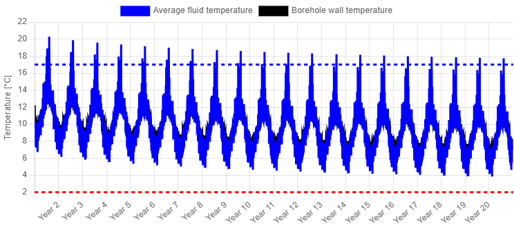
In the graph below, you can see two lines: the average fluid temperature in the borefield and the borehole wall temperature (which is underneath and nearly visible as a sort of shadow of the other line). These lines illustrate how the borefield behaves over the years (we see a downward trend in this case, which is called the imbalance) and from hour to hour. The concept of borefield design lies now in keeping these fluid temperatures within a certain range. If the fluid crosses these limits, the field is not sized accurately and a larger borefield is required. In what follows, these temperature limits will be discussed.
Minimum fluid temperature
One limit on the fluid temperature is the minimum fluid temperature. For sustainability reasons, we do not want the ground to become frozen over time, which is why most regions put specific design guidelines on the allowed minimum temperature. In most countries, the average fluid temperature should stay above 0°C after 25 years, but in the region of Brussels (Belgium) it is the inlet temperature that should stay above 0°C after 25 years. In Switzerland, the design limit is an average fluid temperature of -1.5°C after 50 years.
Besides legal reasons, there are also sustainability and technical reasons. In order to not harm the life in the ground, we want to stay away from freezing the ground. Besides that, ice is a bad conductor of heat, so when the borehole freezes, an ice layer forms, effectively insulating the borehole, which causes a decrease in your system’s efficiency or perhaps even a failure.
Since grout is also porous, moisture is typically present, and when the borehole freezes, this moisture expands and can cause cracks in the grout. Over the years (or multiple freezing cycles), these crack can grow, causing significant damage to the structure of the borehole and (potentially) the thermal performance.
Maximum fluid temperature
Besides the minimum fluid temperature limit, there is also a maximum limit. Besides legal requirements (typically below 25°C average or injection fluid temperature), there is also a technical reason.
If passive cooling is required, we typically want to stay below the 16-18°C as an average fluid temperature, that way, we have 17-19°C available on the other side of the heat exchanger to cool our building, which is typically the highest you can go to ensure enough cooling capacity.
When active cooling is used, this 17°C threshold is no longer a strict requirement, since the heat pump can dump heat in warmer borefields.
Two categories of borefield design
Now that the goal of our borefield design is clear — staying within predefined limits — let us take a look at two different approaches on how to calculate the required borefield size: rule of thumb or using borefield design software.
Rules of thumb
Like in any other HVAC field, there are a lot of different ways to engineer a system. The geothermal domain is no different. When looking at literature, there are four different levels of borefield sizing accuracy mentioned, ranging from linear rules of thumb to hourly simulations (this will be discussed in a later part). The latter is, of course, the most accurate, but often, in practice, rules of thumb are still used for borefield sizing. These rules come in the form of a specific power per borehole length (such as 30W/m borehole), and offer the designer a quick way to size a system by just dividing the required peak load by this factor.
However, what are the important criteria that gave rise to this constant value? Is it for a shallow or a deeper borefield? Is it designed to work with peak heating, or also for peak cooling? Does it assume laminar or turbulent flow? What type of heat exchanger did they use? What were the ground properties, the borefield configuration …
Relying on rules of thumb does not give any insight in your design, since they make abstraction of the temperature profile discussed previously. It is hence unclear if your borefield is oversized or undersized.
Borefield design software
When designing a geothermal borefield, numerous decisions must be made. Not only must you determine the total required borehole length, but also the borefield configuration, depth and borehole internals. Parameters such as fluid regime (laminar or turbulent) are particularly crucial for your final design. With specialised design software like GHEtool Cloud, you can input all these project-specific parameters and calculate the number of boreholes required to stay within the temperature limits. This ensures your borefield is consistently sized correctly and, therefore, economically optimized. The disparities between a result derived from a rule of thumb versus one from borefield design software can be quite significant.
Comparison between tools and rules of thumb
To illustrate the contrasting design outcomes between sizing with rules of thumb and GHEtool Cloud, a comprehensive analysis was conducted. Three diverse buildings—an auditorium, an office, and a multi-family residential building—were dynamically simulated with an hourly resolution to capture the variation in thermal demand accurately. Next, these hourly heating and cooling demand profiles were used as inputs for GHEtool to size the borefield across numerous scenarios: laminar or turbulent flow, varying grout thermal conductivity, deep or shallow boreholes …
Each simulation is represented as a distinct red dot in the figures provided below, showing the range of design possibilities and the significant impact of utilising GHEtool for precise borefield sizing.
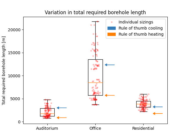
All the red dots in the figure above represent accurately sized borefields, with variations stemming from differences in design inputs. When comparing the range of potential sizes obtained through GHEtool with the single value derived from a rule of thumb, it is clear that the latter offers minimal insight into the accuracy and robustness of borefield design.
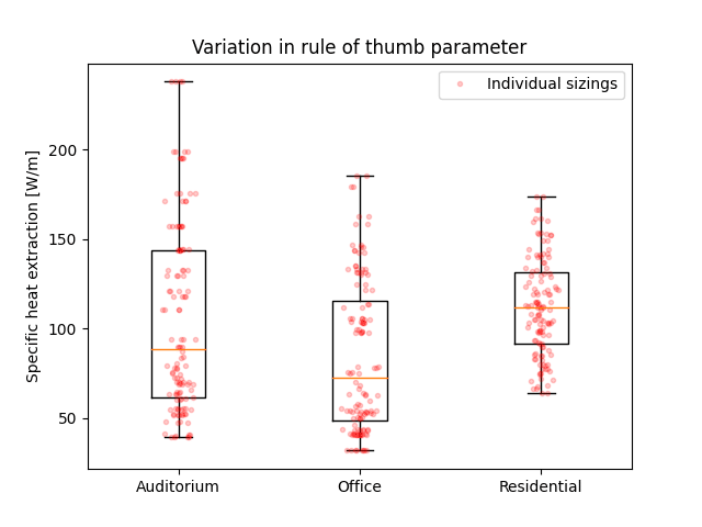
But perhaps the rule of thumb of 30W/m was just wrong? Well, if we were to reverse engineer the rule of thumb based on the known peak powers and the different sizings from the previous figure, the specific heat extraction/injection ranges from 30 to 230W/m. This wide range is an inherent consequence of the design flexibility you have as a borefield designer, that can simply not be narrowed down into a one-size-fits-all number.
Conclusion
The goal of borefield design is clear: we want to make sure that our fluid temperatures stay within certain limits, either for legal requirements or based on good practice. It is not possible to obtain this certainty when working with rules of thumb, since they make abstraction of the temperature profile and directly correlate the required size with the demanded peak powers.
As a geothermal designer, a tool like GHEtool gives you everything you need to accurately size borefields, taking into account all the important aspects like the ground properties, the thermal demand and the heat pump efficiency. These will be discussed in the next chapters.
References
- SIA 384/6
- Selçuk E., Bertrand F. (2016). Freeze damage of grouting materials for borehole heat exchanger: Experimental and analytical evaluations. Geomechanics for Energy and the Environment, Volume 5, Pages 29-41, ISSN 2352-3808, https://doi.org/10.1016/j.gete.2015.12.002.
- Peere, W. (2024). Are Rules of Thumb Misleading? The Complexity of Borefield Sizing and the Importance of Design Software. IEA HPT Magazine 42(1), https://doi.org/10.23697/7nec-0g78.