
The hydraulic design of your borefield—specifically the decision to place your boreholes in series, parallel, or a combination of both—can significantly impact the total required borehole meters. This article will guide you through how to define the different hydraulic design options in GHEtool Cloud.
Essential Concepts
The hydraulic decisions you make as a designer directly affect the total required borehole meters. Choices such as whether to use a single or double U-tube (internal borehole hydraulic design) or how to connect boreholes in series or parallel (external borehole hydraulic design) impact the flow regime through the borefield. This, in turn, affects the overall design, as discussed in previous articles.
!Note
If you have not yet read our article on Reynolds numbers and the difference between laminar and turbulent flow, we recommend reviewing it first. This knowledge will enhance your understanding of the concepts presented here.
Defining Flow Rate in GHEtool Cloud
In GHEtool Cloud, only one parameter for hydraulic design needs to be entered—the flow rate per borehole. This parameter can be found under the ‘Borehole Resistance’ > ‘Fluid Data’ tab.
!Caution
You must enter the flow rate per borehole, not per tube or heat exchanger. GHEtool will automatically calculate key information such as pressure drop, Reynolds number, fluid regime, and borehole thermal resistance based on this input. For clarity, figures within GHEtool display the resulting flow rate per tube, but you should always enter the flow rate for the entire borehole.!Stay tuned
Pressure drop calculation deserves an article on its own. The explanations related to pressure drop below are hence rather brief. Currently, we are working on extending the methods for calculating pressure drop with GHEtool Cloud and once that is finished, a full scale article on the topic will be released.
Two Approaches to Hydraulic Design
There are two general approaches to the hydraulic design of a borefield:
- Top-down approach: Start with the total system flow rate and calculate the resulting flow rate through each borehole.
- Bottom-up approach: Define the required flow rate through each borehole and calculate the total system flow rate.
Although these approaches differ in their starting points, the design logic remains the same.
!Note
Designing based on flow rate alone can be misleading. The system’s pump must be able to handle the pressure drop of the entire borefield. For larger systems, it’s crucial to calculate the total pressure drop and ensure the pump is adequate. For smaller residential projects, where the heat pump’s internal pump manages the pressure, verify with the manufacturer that it can meet these requirements.
Different Hydraulic Designs
There are four primary hydraulic design archetypes, plus a combined case, which can serve as a model for more complex systems. These archetypes are based on the following combinations:
- Internal borehole design: Single U-tube or Double U-tube
- External borehole design: Parallel or Series connections
Single U tube – Parallel
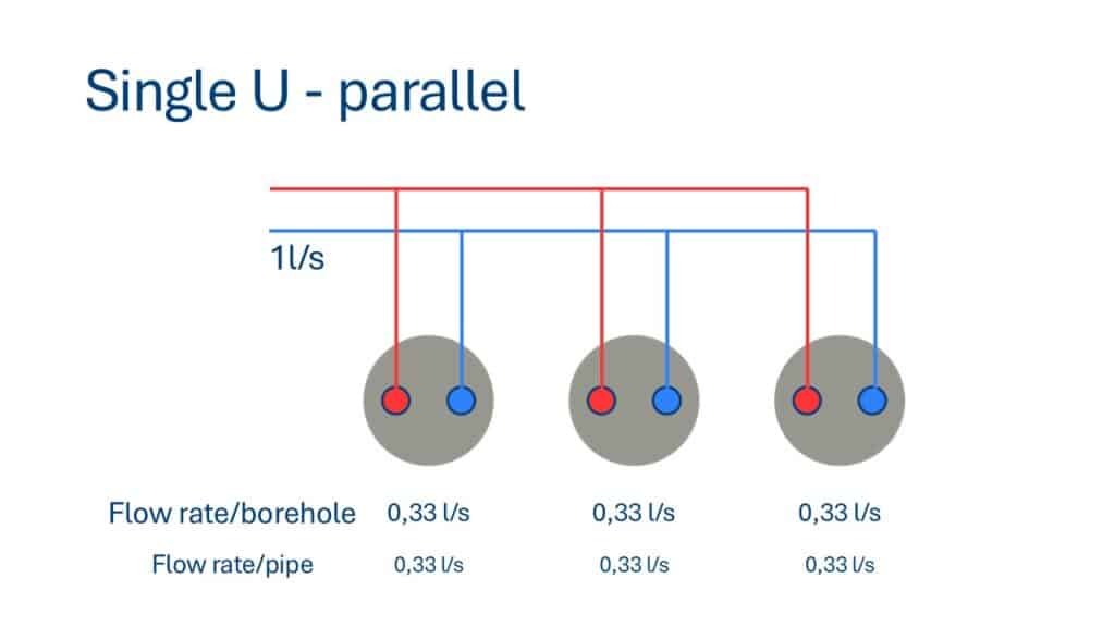
In this setup, the boreholes are connected in parallel, and the total system flow rate is split equally across the boreholes. For instance, if the system flow rate is 1 l/s and there are 3 boreholes, each borehole will receive 0.33 l/s. This is the flow rate you enter in GHEtool Cloud.
!Note
The pressure drop for parallel systems is equal across all boreholes. If one borehole experiences a 20 kPa pressure drop, the combined pressure drop for all boreholes will also be 20 kPa. Additional pressure drop in horizontal tubing must be considered.
Single U tube – Series
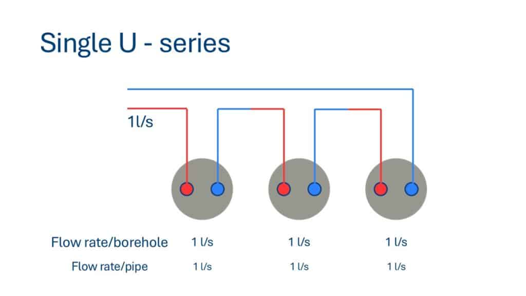
Here, boreholes are connected in series, meaning the total system flow rate flows through each borehole consecutively. If the system flow rate is 1 l/s, this same flow rate passes through every borehole.
!Note
For series connections, you add the pressure drop of each borehole. For example, if one borehole causes a 20 kPa pressure drop, then three boreholes connected in series would result in a total pressure drop of at least 60 kPa, not accounting for pressure drop in horizontal piping.
Double U tube – Parallel
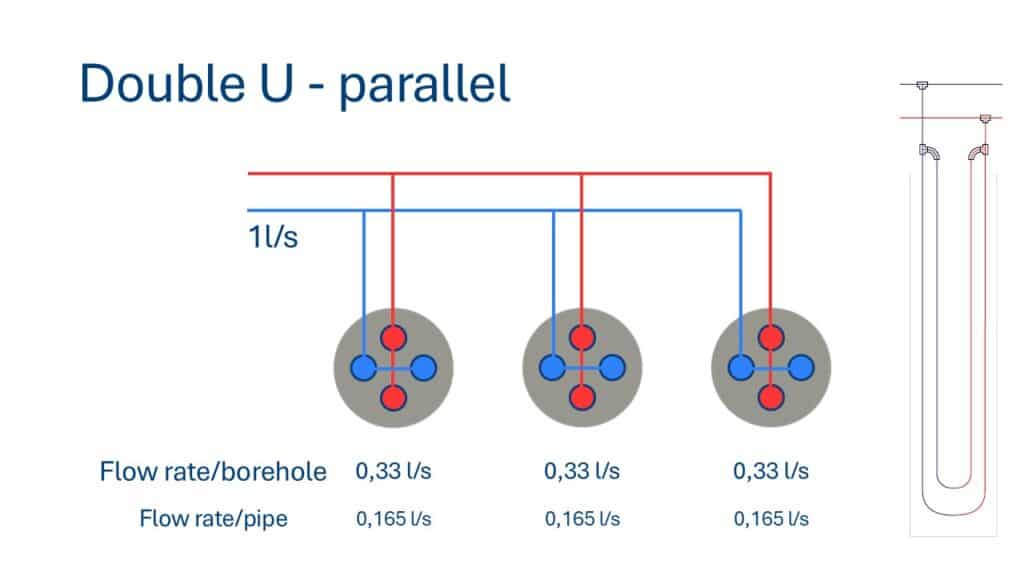
When boreholes with double U-tubes are connected in parallel, the flow is split both externally and internally. The system flow rate is divided equally among the boreholes, and the flow in each borehole is further divided between the two U-tubes. For a system flow rate of 1 l/s with 3 boreholes, each borehole receives 0.33 l/s, and each U-tube within a borehole receives 0.165 l/s.
Double U tube – series
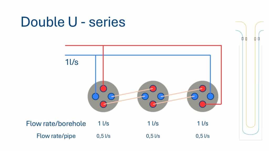
In a double U-tube series configuration, the U-tubes are not internally connected. Instead, each U-tube in a borehole operates as an independent path. Flow moves through each U-tube in the borehole, effectively creating two parallel flow paths per borehole. The system flow rate of 1 l/s is divided across two parallel U-tube paths in each borehole, so each pipe receives 0.5 l/s.
Combined

Many large borefields use a combined design to balance pressure drop and flow rate requirements. For instance, a system with 6 boreholes might group them into two sets of three series-connected boreholes. These two groups are then connected in parallel.
To analyse this system, begin at the borehole level. Each borehole in a series group receives the total group flow rate. If each borehole in the system requires a 0.5 l/s flow rate, and each series group contains three boreholes, then the total group flow rate is 0.5 l/s. Since the two groups are connected in parallel, the system’s total flow rate is 1 l/s (0.5 l/s per group × 2 groups).
!Note
Total pressure drop for the combined system is calculated by summing the pressure drops of the boreholes in each series group. Since the groups are in parallel, this combined pressure drop does not increase due to parallel connection. However, be sure to account for horizontal piping and corner losses (so called ‘local losses’).
Conclusion
Choosing the right hydraulic design for your borefield can significantly impact the total required borehole length and overall system efficiency. By understanding the implications of parallel vs. series connections and the differences between single and double U-tube designs, you can make more informed decisions. GHEtool Cloud simplifies this process by allowing you to input a single flow rate per borehole, with automated calculations for pressure drop, Reynolds number, and borehole thermal resistance.
References
- Watch our video explanation over on our YouTube page by clicking here.