
Previously, all fluid temperatures in GHEtool Cloud were averages of the inlet and outlet temperatures. In our latest update, we added the option to work directly with the inlet or outlet temperatures as well. Learn everything there is to know in this article!
Temperature profiles in GHEtool
Whenever you are designing a borefield, you want to keep your fluid temperatures within certain limits, which can vary depending on your region, project, type of antifreeze, etc. Historically, the fluid temperatures in the temperature profiles (like, for example, the one below) were the average temperatures of the borefield inlet and outlet temperatures. This definition is also used by other geothermal design software, such as Earth Energy Designer.
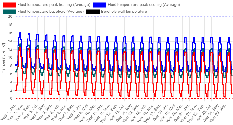
The reason why the average fluid temperature is so common is because of its direct link to the concept of the effective borehole thermal resistance (more information in this article). To recap, the effective borehole thermal resistance is defined as the steady-state heat transfer resistance between the average borehole wall temperature (the average of the entire borehole wall) and the average fluid temperature (the average of all the fluid inside the borehole).
During the simulation, the borehole wall temperature is first calculated using the monthly (or hourly) extraction and injection loads and the g-functions (more information in this article). Once the borehole wall temperature is known, the effective borehole thermal resistance is calculated using the variable fluid and flow properties. Using these two results, the average fluid temperature can be calculated directly based on the definition of the borehole thermal resistance.
However, since the flow rate is also known (either constant or variable), the temperature difference between the borefield inlet and outlet is also known, based on the following formula:
$$\dot{Q}=\dot{m}C_p\Delta T$$
where $\dot{Q}$ is the extraction/injection power (kW), $\dot{m}$ is the mass flow rate (kg/s) through the borefield, $C_p$ is the specific heat capacity of the fluid (kJ/(kgK)), and $\Delta T$ is the temperature difference between the borefield inlet and outlet.
Since the average fluid temperature is known, together with the mass flow rate, the power, and the specific heat capacity (at each month/hour), the inlet and outlet temperatures can also be calculated. This gives us the option to work with any of the three fluid temperatures in GHEtool, each of which tells a different story.
!Note
The fluid temperature calculation in GHEtool is currently based on the traditional steady state model of the effective borehole thermal resistance. However, as discussed before, this has some limitations related to the short term transient behaviour of the system. Currently, research is being carried out together with universities on how this could be improved in a future update.
Three fluid temperatures
From now on, three fluid temperatures can be simulated in GHEtool: the average fluid temperature, the inlet fluid temperature, and the outlet fluid temperature. All three are discussed briefly below.
!Note
Whereas the average fluid temperature can also be calculated using a constant, measured effective borehole thermal resistance, this is not feasible for the inlet and outlet fluid temperatures because they are calculated using the flow rate.
Average fluid temperature
The average fluid temperature is the most straightforward temperature to work with, due to its direct coupling to the borehole wall temperature. The advantage is that it abstracts away part of the effect of the flow rate (although this is considered via the borehole thermal resistance), meaning that, whether the flow regime is 3 °C/0 °C or 5 °C/−2 °C, the average fluid temperature is always 0 °C. This, however, means that if you want to control the absolute minimum and maximum fluid temperatures, the average fluid temperature is not directly suited.
Inlet fluid temperature
The inlet fluid temperature is the temperature entering the borefield and could be described as the worst case fluid temperature, since it is always the coldest during extraction and the warmest during injection. This is because the fluid entering the borefield is also the fluid leaving the heat pump. When your heat pump is heating the building, it extracts energy from the primary circuit, meaning that the fluid at the heat pump outlet is the coldest fluid in the entire circuit (and vice versa for cooling/injection).
If you want to put strict limits on the temperatures of your borefield, the boundaries on the inlet fluid temperature will ensure that you have essentially covered all potential temperatures, ensuring that there is no violation of this limit.
Outlet fluid temperature
The outlet fluid temperature, finally, is the temperature leaving the borefield and is the best case fluid temperature. During extraction, a cold fluid is injected into the borefield and is heated by the ground, resulting in a higher temperature at the borefield outlet. Similarly, during injection, a warm fluid is injected into the borefield, where it cools down, leading to a lower fluid temperature at the outlet.
This outlet fluid temperature can be useful when selecting the correct heat pump, since the power that can be delivered by the heat pump depends on the temperature entering its evaporator (or condenser, in the case of active cooling). If your machine has a rated power at a heat pump inlet temperature of 0 °C and that is the only thing you care about, you can design using the outlet fluid temperature.
Example in GHEtool Cloud
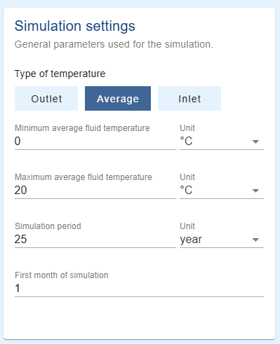
From now on, under the ‘General’ tab in the simulation settings, you can select which of the three fluid temperatures you want to design with. If you select Inlet, all the respective fluid temperatures will be redefined as inlet fluid temperatures.
!Note
When you are working with active and passive cooling, the temperature threshold remains defined based on the average fluid temperature.
In the temperature profile below, a simulation is carried out with four boreholes of 100 m and a variable flow rate with a constant temperature difference of 3 °C between the borehole inlet and outlet. It can be seen that, with a minimum average fluid temperature of 0.46 °C, the fluid stays nicely within the limits. However, as mentioned before, this does not mean that the absolute minimum fluid temperature does not cross the 0 °C threshold. Therefore, a simulation using the inlet fluid temperature is carried out.
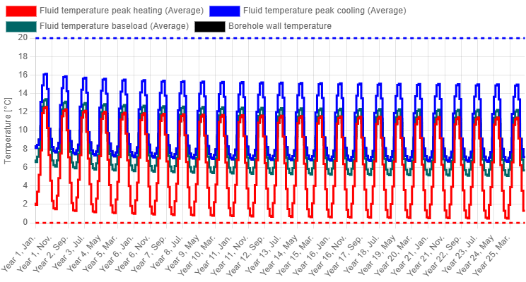
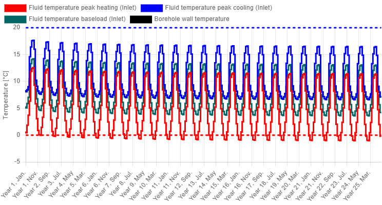
When the same simulation is carried out using the inlet fluid temperatures, the fluid temperature now drops to −1.04 °C. As mentioned before, the inlet temperatures are always the lowest in the system, so even if the average fluid temperature is positive, the inlet temperature can still be negative. If you want your absolute minimum (and vice versa maximum) temperature to stay within certain limits, please work with the inlet fluid temperatures.
Finally, the outlet fluid temperatures are shown below. They only drop to 1.96 °C and are therefore the most optimistic temperatures.
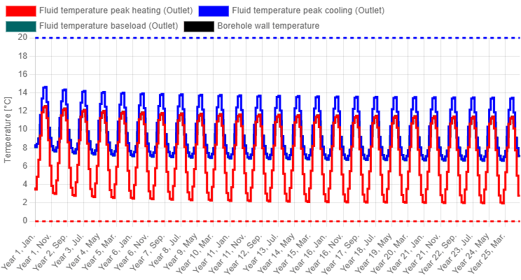
Of course, selecting different fluid temperatures can also result in a different required design. If the borefield above were sized according to each of these three temperatures, the required borehole lengths would be 381 m, 434 m, and 338 m, respectively. This indicates that a design based on the inlet fluid temperature leads to the largest required borefield, while one based on the outlet fluid temperature leads to the smallest, which is in line with the discussion above.
Conclusion
In this article, the three different fluid temperatures (average, inlet, and outlet) are discussed. The average fluid temperature is typically used in borefield design, since it is directly linked to the borehole wall temperature via the effective borehole thermal resistance. However, it does not guarantee that the absolute minimum and maximum fluid temperatures are within the limits. To guarantee this, the inlet fluid temperatures should be used. The outlet fluid temperatures can be used to guarantee that the heat pump can deliver its rated power.
This was also illustrated in an example in GHEtool, where a design based on the inlet fluid temperature resulted in the largest required borefield size, guaranteeing that all fluid temperatures stay within the set limits.
References
- Watch our video explanation over on our YouTube page by clicking here.