
En el último capítulo, investigamos la cuestión: “¿Qué es mejor: un tubo en U simple o doble?” desde una perspectiva térmica. En este capítulo, utilizamos los conocimientos de la Parte 4 de este curso para examinar la misma cuestión desde una perspectiva hidráulica.
Aspectos hidráulicos
Al discutir los aspectos hidráulicos relacionados con la elección del intercambiador de calor geotérmico, la atención se centra en la caída de presión del sistema. Como se ha comentado en la parte 4.1, esta pérdida de carga se compone tanto de las pérdidas locales (codos, uniones, etc.), principalmente en la parte horizontal del sistema, como de las pérdidas por fricción, que son un aspecto inherente al flujo de fluidos a través de tuberías. Para mantener baja la potencia de la bomba y el consumo eléctrico correspondiente, es preferible una caída de presión baja.
La caída de presión total a través de la perforación se define como$$\Delta P = \left(f\cdot \frac{L}{D}+\sum{K}\right)\cdot \frac{\rho v^2}{2}$$donde $\Delta P$ es la caída de presión en (Pa), $f$ es el factor de fricción adimensional de Darcy-Weisbach, $L$ es la longitud de la tubería en (m), $D$ es el diámetro de la tubería en (m), $\sum{K}$ es la suma de todos los factores de pérdida locales, y $\rho$ y $v$ son, respectivamente, la densidad del fluido en (kg/m³) y la velocidad del fluido en (m/s).
- $\Delta P \propto \dot{Q}^2$ (siendo $\dot{Q}$ el caudal en (m³/s))
- $\Delta P \propto D^{-5}$
Ambas relaciones desempeñarán un papel central en el debate que se desarrolla a continuación.
En segundo lugar, en Parte 4.2, el consumo eléctrico de la bomba se definió como$$E_e=\frac{{suma_limits_{i=0}^{8760 n}{\dot{Q}(i)\cdot 1000\Delta P(i)}}{n\eta}$$donde $E_e$ es el consumo eléctrico de la bomba en (kWh/año), $n$ es el número de años, $\dot{Q}(i)$ es el caudal en la hora $i$ en (m³/s), $\Delta P$ es la caída de presión en la hora $i$ en (Pa), y $\eta$ es el rendimiento de la bomba.
Para responder a la pregunta que nos ocupa desde una perspectiva hidráulica, en los siguientes apartados se harán las siguientes comparaciones:
- Mismo diámetro de tubo pero distinto número de tubos
- Diferente diámetro de tubo y el mismo número de tubos
- Distintos diámetros de tubo y distintos números de tubos
Por último, se analizará el consumo eléctrico de la bomba en función del tubo en U simple frente al doble.
Todas las simulaciones que figuran a continuación se han realizado con un pozo de 100 m de profundidad y 70 cm de profundidad enterrado. El fluido utilizado es MPG con 25 v/v% a 5°C. Todas las tuberías tienen una clasificación de presión PN16 (SDR11). El diámetro de tubería por defecto es de 32 mm. Todas las desviaciones de los supuestos anteriores se mencionan explícitamente a continuación.
Mismo diámetro, distinto número de tubos
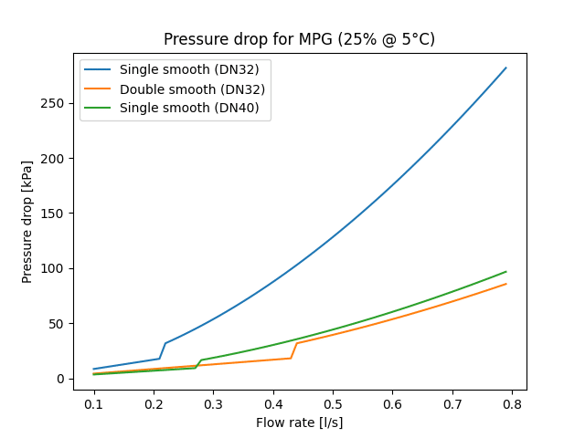
Como primer paso para responder a la pregunta del tubo en U simple frente al doble, se realiza una comparación directa entre una sonda DN32 simple y una doble. Esta comparación se muestra en el gráfico siguiente.
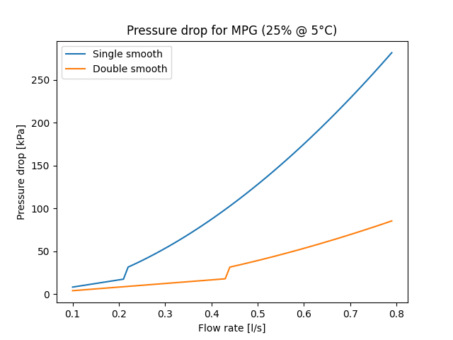
Como puede verse, el tubo en U doble siempre tiene una pérdida de carga menor que el tubo en U simple. Esto se debe a que, en el caso de un tubo en U simple, 100% del caudal pasa por esa tubería, mientras que en el caso de un tubo en U doble cada tubería transporta sólo 50% del caudal total. Como la pérdida de carga es cuadráticamente proporcional al caudal, el tubo en U simple siempre tiene una pérdida de carga mayor.
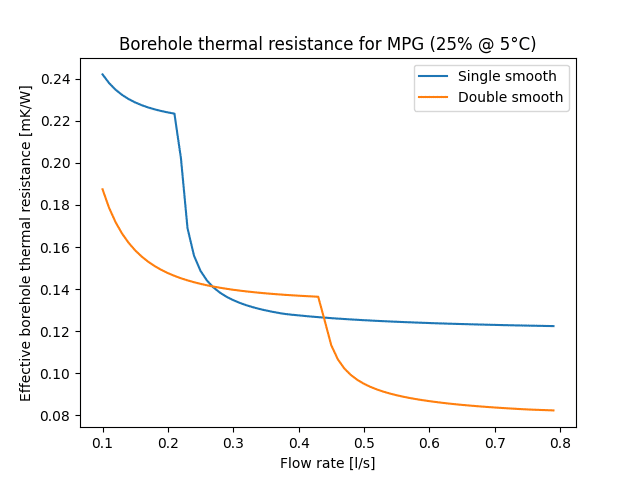
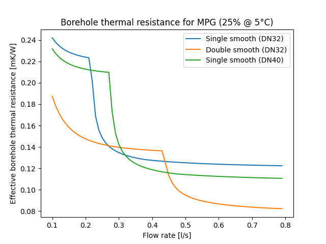
Cuando los resultados hidráulicos anteriores se comparan con su contraparte térmica a continuación, como se discute en el último capítulo, En el caso de los tubos en U dobles, queda claro que para caudales de hasta 0,25 l/s y de 0,45 l/s en adelante, el DN32 doble es la mejor solución tanto desde el punto de vista térmico como hidráulico. El tubo en U simple, aunque tiene una menor resistencia de perforación entre 0,25 l/s y 0,45 l/s, siempre tiene una mayor pérdida de carga asociada. Su mejor resistencia de perforación se “paga” con una peor pérdida de carga.
Distinto diámetro, mismo número de tubos
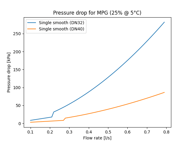
Si damos un pequeño rodeo y comparamos dos tubos en U sencillos con diámetros diferentes, podemos ver claramente que el DN40 sencillo supera al DN32 al mostrar una caída de presión menor. Esto se debe a que, con un diámetro interior mayor, la caída de presión disminuye con la quinta potencia del diámetro.
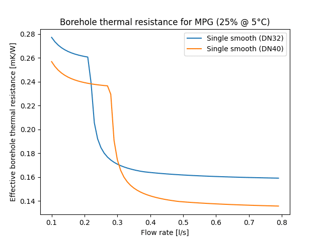
Cuando este gráfico se compara de nuevo con su homólogo térmico, hay una región superpuesta, por debajo de 0,2 l/s y por encima de 0,3 l/s, en la que el DN40 único supera al DN32 único tanto desde el punto de vista térmico como hidráulico.
Diferentes diámetros y número de tubos
Teniendo en cuenta lo anterior, volvamos a la discusión sobre el tubo en U simple frente al doble, esta vez con diferentes diámetros de tubo. A continuación, se muestra la caída de presión en una comparación entre un tubo en U DN32 simple, un DN40 simple y un DN32 doble.
Está claro que hay un intervalo entre 0,1 y 0,25 l/s en el que el DN40 simple tiene una pérdida de carga menor que su homólogo DN32 doble. Aunque esto pueda parecer contradictorio a primera vista, dado que la velocidad de flujo es efectivamente mayor en el caso del DN40, el mayor diámetro de la tubería da lugar a una menor superficie de contacto entre la pared de la tubería y el fluido, lo que se traduce en una menor pérdida de carga global en este rango laminar.
Curiosamente, si volvemos a comparar esto con la parte térmica de la historia, podemos ver que ya no hay ninguna región superpuesta en la que el DN40 único supere tanto en el frente térmico como en el hidráulico. Cuando tiene la menor pérdida de carga (<0,25 l/s), la resistencia térmica efectiva de la perforación es peor y, cuando ésta se convierte en la mejor opción (0,3-0,45 l/s), la pérdida de carga es mayor. En cambio, para caudales superiores a 0,45 l/s, el doble DN32 ofrece mejores resultados tanto desde el punto de vista térmico como hidráulico.
Energía de bombeo y bombas de calor modulantes
La caída de presión es importante para la selección de la bomba y para garantizar que el campo de sondeo pueda funcionar realmente en las condiciones para las que se diseñó, pero es sólo una parte de la historia. La otra parte es el consumo eléctrico de la bomba. Con una mayor caída de presión, la bomba consume más electricidad, lo que supone mayores costes de funcionamiento. En la tabla siguiente se comparan las sondas DN32 simple, DN40 simple y DN32 doble.

Para un caudal dado de 0,3 l/s, está claro que el DN32 único tiene una pérdida de carga significativamente mayor y, por tanto, también un consumo anual de electricidad más elevado en comparación con las otras dos opciones. Esto puede explicarse por el mayor número de Reynolds, que ya indica un régimen de flujo turbulento o transitorio. Como ya se ha dicho, el DN40 simple tiene una pérdida de carga menor que el DN32 doble, con el correspondiente menor consumo eléctrico, aunque la velocidad del flujo es mayor, como indica el mayor número de Reynolds.
Históricamente, esto habría sido el final de la historia. Sin embargo, dado que las bombas de calor modernas son cada vez más modulantes, el caudal que circula por el pozo ya no es constante, como se explica en la parte 3.3. Esto significa que si el caudal de diseño es de 0,3 l/s, la mayoría de las veces el caudal real será aproximadamente 70% de ese valor, es decir, 0,21 l/s. La situación para este caudal se muestra en la tabla siguiente.

De la tabla anterior se desprende que el consumo eléctrico real es inferior en todos los casos, pero sobre todo en el DN32 simple. Sigue mostrando el valor más alto, pero ya es más aceptable que con el caudal de diseño.
En la siguiente sección, se presentará un ejemplo real en GHEtool Cloud para el caso de un edificio auditorio con estos tres diseños de sonda diferentes y tanto un caudal variable como constante.
Ejemplo en GHEtool
En las secciones siguientes, se realiza una comparación entre un DN32 simple, un DN40 simple y un DN32 doble para un edificio de auditorios con refrigeración activa. Esta comparación se realiza tanto para un caudal variable como para un caudal constante.
Simulación con caudal variable
El siguiente gráfico muestra el perfil horario de temperatura de un campo de sondeo geotérmico que da servicio a un auditorio. La simulación se realizó utilizando un tubo en U DN32 doble con un caudal variable y una diferencia de temperatura constante de 4 °C en todo el campo de sondeo, tanto en modo de calefacción como de refrigeración.
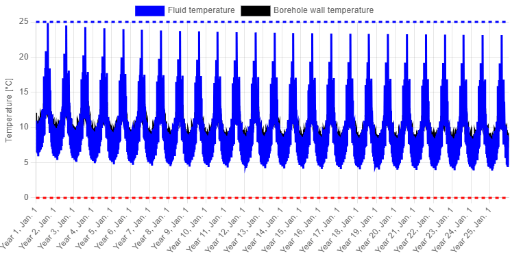
Dado que la demanda máxima de refrigeración (90 kW) es significativamente superior a la demanda máxima de calefacción (30 kW), la demanda de refrigeración es en realidad el factor limitante en este caso, tanto térmica como hidráulicamente, con un caudal de 6,79 l/s a través de todo el campo de perforación en comparación con 1,64 l/s para la extracción. La caída de presión durante la refrigeración es de 119 kPa en este caso, mientras que sólo es de 13,58 kPa durante la calefacción.
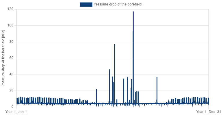
El siguiente gráfico de caída de presión horaria muestra claramente que, debido a los caudales variables, la caída de presión es significativamente menor la mayor parte del tiempo (10 kPa o menos). Por tanto, el consumo eléctrico estimado de la bomba es de unos 37 kWh/año.
Cuando se realiza la misma simulación para una sola sonda DN32, la caída de presión es mucho mayor, alcanzando 386 kPa durante la inyección y 29 kPa durante la extracción. Esto se debe a que 100% de los 6,79 l/s fluyen ahora por una sola sonda en U. El consumo eléctrico anual estimado de la bomba en este caso es de 83 kWh/año. A continuación se muestra también el gráfico de caída de presión horaria para este caso de tubo en U único, donde se ve claramente que los picos de caída de presión son significativamente mayores, aunque la caída de presión media es de nuevo mucho menor.
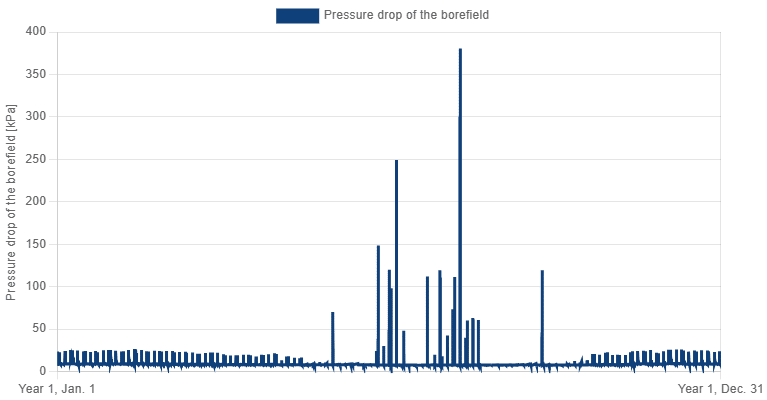
El caso de la DN40 simple es bastante similar al de la DN32 doble, con una pérdida de carga máxima de 133 kPa y un consumo eléctrico estimado de la bomba de 32 kWh/año, que es inferior al del caso de la DN32 doble. Como se ha comentado anteriormente, debido al menor caudal durante la extracción, ambas situaciones (DN40 simple y DN32 doble) se encuentran en régimen laminar, lo que significa que el DN40 simple tiene una pérdida de carga menor en este caso. A lo largo de todo un año, esto se traduce en un menor consumo eléctrico.
Simulación con caudal constante
Como comparación final, se realizaron las mismas tres simulaciones utilizando el caudal de diseño de 6,79 l/s como caudal constante. A continuación se muestra el gráfico de caída de presión horaria para el tubo en U doble.
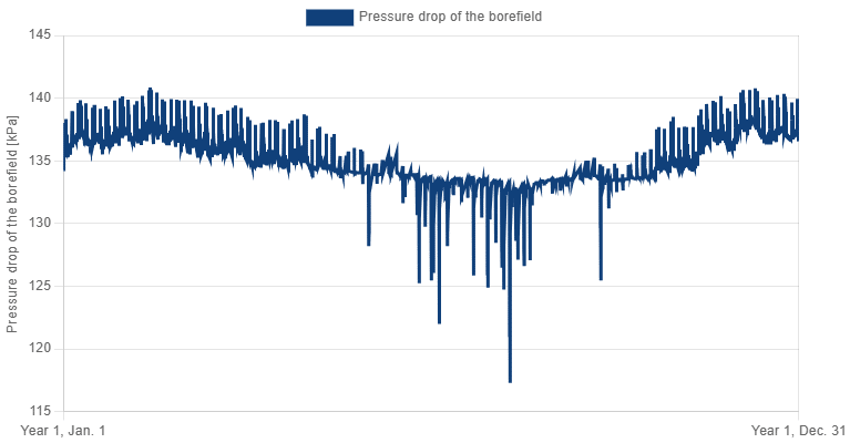
Como el caudal es ahora constante, el consumo total de electricidad es de 8079 kWh/año, en lugar de los 37 kWh/año del caso de caudal variable. La pérdida de carga máxima es ahora de 145 kPa.
En el caso de la DN32, la situación es aún peor, con una caída de presión máxima de 481 kPa y un consumo eléctrico total de la bomba de 26734 kWh/año, que es cuatro veces la electricidad necesaria para calentar el auditorio. Como la carga casi nunca es nula, la bomba está casi siempre en funcionamiento, lo que supone un consumo eléctrico muy elevado.
Para la DN40 simple, la caída de presión máxima al trabajar con un caudal constante fue de 165 kPa, y el consumo eléctrico de la bomba fue de 9172 kWh/año.
Conclusión
En este capítulo se ha tratado la cuestión “¿Qué es mejor: el tubo en U simple o el doble?” desde una perspectiva hidráulica. Si los diámetros de las tuberías son idénticos, un tubo en U doble siempre tiene una pérdida de carga menor que su homólogo simple. Esto implica que hay rangos de caudal en los que el tubo en U doble es ventajoso tanto desde el punto de vista térmico como hidráulico.
Cuando se trabaja con diferentes diámetros y se compara un DN40 simple con un DN32 doble, la situación se vuelve algo más compleja. En este caso, hay rangos de caudal en los que el DN40 simple tiene la menor caída de presión, aunque no la menor resistencia de perforación. No hay ningún rango en el que un tubo en U sencillo tenga un mejor rendimiento térmico e hidráulico, ya que las ventajas de la turbulencia se ven compensadas por una mayor caída de presión.
La comparación de estas tres configuraciones de sonda en GHEtool Cloud para un edificio de auditorios ilustra una vez más la importancia de utilizar un caudal variable al diseñar los campos de sondeo, así como lo pequeña que puede ser la diferencia de consumo eléctrico de la bomba entre un tubo en U simple y uno doble si se compara con la demanda total de electricidad para calefacción y refrigeración.