
In this chapter, the modelling of the Powerwave Coax from Jansen, using direct numerical fluid dynamics calculations to model the fluid behaviour in the annulus, is explained.
JANSEN powerwave coax
The JANSEN powerwave coax is a coaxial geothermal heat exchanger developed by the company Jansen from Switzerland. It is a coaxial pipe with an outer diameter of 63 mm and an inner pipe of 32 mm, both with a wall thickness of 2.9 mm. What makes this pipe unique is the corrugated outer surface, which both increases the heat transfer area to the grout (and in the end the borehole wall) and changes the fluid behaviour inside the probe by enhancing the turbulence.
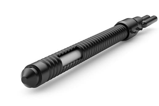
The equations that were developed for coaxial pipes, namely for the part between the outer and inner pipe, which is also called the annulus, are not valided for the probe at hand. Due to the corrugated surface, the cross-sectional area of the annulus is not constant, meaning that the flow velocity will vary along the pipe length. This of course changes the fluid behaviour significantly, requiring once again the use of computation fluid dynamics (CFD) and more precisely direct numerical simulation (DNS) just like as was the case for the TurboCollector and the MuoviELLIPSE.
More information on the JANSEN powerwave coax itself can be found on the Jansen website.
Besides the coaxial configuration, Jansen also sells the powerwave as a single or double U-tube. Since these pipes are non-coaxial, the fluid behaviour is different therefore requiring a study on its own, which, at the moment of writing, is not yet finished.Model development
In order to model the JANSEN powerwave coax, the results from the CFD simulations are discussed first after which the Nusselt number correlations and the correlation for the friction factor are discussed.
CFD simulations
In the figure below, the results of the are shown for different Reynolds numbers, ranging from 600 to 2000.
Since the cross-sectional area in the annulus always changes it is important to select a definition for the area and perimeter that remain constant throughout the length of the pipe so that the Reynolds number and all corresponding parameters can be uniquely be defined. Peere et al. (2027) defined both the area and the perimeter at the average inner diameter of the outer pipe, which is 53.2 mm. Using the definition of the hydraulic diameter, the Reynolds number can than be uniquely defined.

When looking at the different simulations above, it is clear that the case with a Reynolds number of 600 is still completely laminar, which can be seen by the clear distinction between the different colours that indicate the fluid temperature. This temperature gradient is exactly the laminar boundary layer as discussed in Part 6.1, where all layers are clearly moving next to each other and there is no mixing whatsoever.
When the flow rate is increased until a Reynolds number of 800 to 1000 is achieved, this clearly changes. At Re=800 the first vortices inside the wells are visible, but they mainly stay within the well itself, only causing minor disturbance in the overall flow inside the pipe’s annulus. At Re=1000 these disturbances start to propagate through the rest of the probe, reducing the laminar region significantly. Therefore, the onset of turbulence is said to be at Re=1000, instead of the traditional 2300 for regular smooth pipes.
For higher Reynolds numbers, this mixing keeps growing, with the laminar region being gone at around Re=1400 and a clearly mixed flow for Reynolds numbers higher than 2000. However, for reasons of consistency, the fully developed turbulent flow is said to start at Re=4000.
Correlation for the friction factor
Using the CFD results above, the friction factor can be calculated for different Reynolds numbers. These calculations as well as the overall correlation is shown below.

Here, the friction factor decreases quite quickly in the laminar regime down to Re=1000 and afterwards stays more or less constant.
Correlation for the Nusselt numbers
In contrast to the correlations developed for the TurboCollector and the MuoviELLIPSE, the powerwave coax requires two different Nusselt number correlations. This is because the fluid in the annulus exchanges heat both with the corrugated outer pipe wall and with the inner pipe. Since the fluid behaviour is, as shown above, clearly different at both wall, two different correlations are developed below.
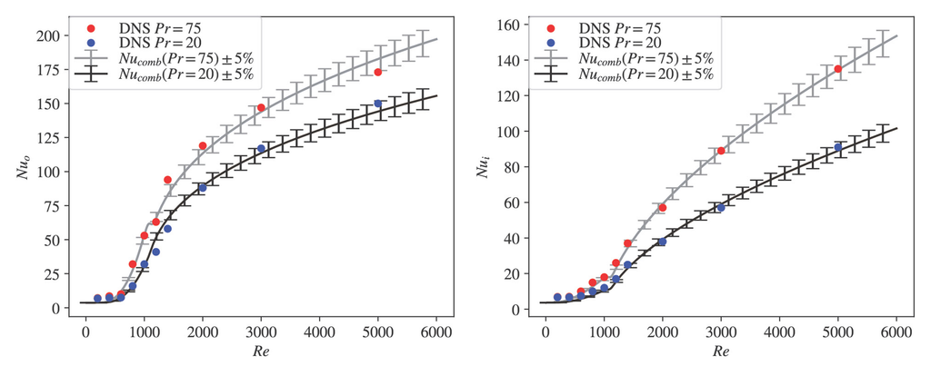
When looking at the situation at the outer wall of the annulus, it is clear that the Nusselt number increases significantly at around Re=1000, which was exactly the onset of the turbulence region. For the inner pipe, this transition starts somewhat later and is less pronounced. Looking at the fluid simulations above, it is also clear that the strongest (and earliest) vortices happen in the wells at the outer pipe rather than close to the inner pipe wall.
Using the weighting function $w$, the Nusselt number for the entire range can be calculated using:
$$w=\left(1+ exp\left[ -4 \left( \frac{Re-1100}{1200-1100}\right) \right] \right)^{-1}$$$$Nu = \left\{ \begin{array}{ll} Nu_{x}^{lam} & Re \leq 1000 \\ (1 – w) \cdot Nu_{x}^{lam} + w \cdot Nu_{x}^{turb} & Re > 1000 \end{array} \right.$$For the full mathematical details, the user is referred to Peere et al. (2027).
Behaviour of the JANSEN powerwave coax
Using the correlations for the Nusselt number and the friction factor, the effective borehole thermal resistance and pressure drop curves can be calculated. These are discussed below.
All simulations below are performed using a borehole with a depth of 100 m and a buried depth of 70 cm. The borehole diameter is 140 mm (unless stated otherwise), the grout thermal conductivity is 1.5 W/(mK), and the ground thermal conductivity is 2 W/(mK). The pipes are placed exactly halfway between the borehole centre and the borehole wall (i.e. at a distance of 35 mm from the borehole centre for a borehole diameter of 140 mm). The fluid used is MPG at 25 v/v% and 5°C.
The double U, is a DN32 PN16 probe and the coaxial pipe is a smooth coaxial pipe with in inner pipe with an outer diameter of 32 mm and an outer pipe with an outer diameter of 63 mm, both with a wall thickness of 2.9 mm, to match the JANSEN powerwave coax parameters.
Effective borehole thermal resistance
The graph below shows the effective borehole thermal resistance for the JANSEN powerwave coax, as well as for a regular coaxial pipe (with the same inner pipe of 32 mm and outer diameter of 63 mm) and a double DN32 probe for comparison.

In the graph above, it is clear that the powerwave coax outperforms the regular coaxial pipe for all flow rates. At around 0.7 l/s, the fluid in the annulus of the regular coaxial pipe also becomes turbulent, enhancing the heat transfer significantly. That is why, at larger flow rates, the regular coaxial pipe converges to the solution of the powerwave coax, which is already turbulent from around 0.2 l/s.
The small bump that is visible at around 0.2 l/s is where the inner DN32 pipe becomes turbulent. This increases the borehole resistance slightly since the thermal short-circuiting between the inner and outer pipe is now smaller.
Since a coaxial pipe is assumed to be at the centre, for the case of a 140 mm borehole, this implies that there is more than 35 mm of grout on all sides of the pipe, insulating the pipe from the wall. Therefore, when the powerwave coax is installed in a smaller borehole of 110 mm, the borehole resistance drops significantly, even outperforming the double U probe over a range of 0.2 l/s to 0.4 l/s.

In the graph above, the borehole resistance is shown for a constant flow rate but for different drilling depths. It is clear that the effective borehole resistance increases with increasing depth, but significantly more for the coaxial probes than for the double U. This is because the thermal short-circuiting between the inlet and the outlet fluid is higher for a coaxial pipe (where the fluid is just separated by a single pipe wall) than for a U-tube, where there is grout and two layers of pipe wall between them.
This larger heat transfer between the entering and returning fluid increases the overall effective borehole thermal resistance and becomes more pronounced when the boreholes are deeper. This is true for any coaxial pipe, not just the powerwave coax.
Therefore, any coaxial pipe benefits from shallower depths as well as smaller drilling diameters. Here, it is clear that for a smaller drilling diameter, the JANSEN powerwave coax can outperform the double U up to a drilling depth of 120 m, when a smaller drilling diameter is used. For the same diameter, the lines converge at very shallow depths.
As said in the beginning of this chapter, the corrugated surface both enhances the turbulence in the annulus region (as was clearly visible in the CFD simulations) and increases the outer surface area to transfer heat to the grout. The first effect is explicitly accounted for in the model, via the Nusselt correlations, but the second effect is discarded.
In the model, the outer pipe wall is assumed to be straight with a constant outer diameter of 63 mm. This is assumed to be a rather conservative assumption, since the surface area in reality is larger. In order to account for this increased surface area, the pipe should be simulated in three dimensions (since there is now an axial dependency) whereby the concept of the effective borehole thermal resistance can no longer be used.
Pressure drop
In the graph below, the pressure drop is shown for the double DN32 probe, the regular coaxial pipe as well as the JANSEN powerwave coax.

It is clear that, once again, the price one has to pay for the better heat transfer and enhanced turbulence is an increased pressure drop. Of all the pipes in the comparison, the JANSEN powerwave coax has the highest pressure drop, due to the turbulence that already starts in the annulus at Re=1000. The regular coaxial pipe needs a much higher flow rate to transition to turbulence and therefore also has the lowest pressure drop.
This, together with the story about the borehole resistance, shows that the JANSEN powerwave already gives a good borehole resistance at very low flow rates, where the pressure drop is also reasonably low. Since a coaxial pipe also benefits from shallower drilling depths, the pressure drop is automatically somewhat lower.
Conclusion
This chapter introduced the JANSEN powerwave coax in GHEtool and discussed its thermo-hydraulic behaviour. Based on a direct numerical fluid dynamic simulation, it was shown that the turbulence in the annular region of the pipe already starts at a Reynolds number of 1000.
Looking at the effective borehole thermal resistance, the JANSEN powerwave coax outperformed the traditional coaxial pipe for all flow rates. It was discussed that any coaxial pipe benefits from a smaller borehole diameter as well as a shallower drilling depth. When the borehole diameter was reduced to 110 mm, the powerwave coax also outperformed the double U DN32 case.
The downside of higher turbulence and better heat transfer is again a higher pressure drop. Therefore, this probe is mostly suited for shallower depths, where the flow rate can be low (due to the enhanced turbulence), thereby minimising the required pump energy.
References
- Peere, W., Hidman, N., Hofstetter, R. (2027). Development of a thermohydraulic model for the JANSEN powerwave coax with direct numerical simulation and its impact on the thermal borehole resistance. In proceedings of Der Geothermiekongress (DGK) 2026, 20-22 October 2026, Potsdam, Germany.
- Hidman, N., Almgren, D., Johansson, K., Nilsson, E. (2026). How internal fins enhance the thermohydraulic performance of geothermal pipes: A direct numerical simulation study. International Journal of Heat and Mass Transfer, 256(3), 128114